Why manual offset correction costs you parts
A good gauge tells the operator that a diameter is 0.020 mm undersize. What happens next depends on the person at the machine. They must compare the value with nominal and limits, decide whether to correct, work out the size and sign of the correction, choose the right offset register and type the number into the CNC.
Every one of those steps can go wrong:
- Sign and decimal mistakes move the process in the wrong direction.
- The wrong register corrects a tool that was not drifting.
- Delayed correction during a busy shift lets more parts drift before anyone acts.
- Over-correction of normal variation makes a stable process unstable.
- No record remains of what was measured, what was decided or what the machine received.
How automatic offset correction works
Automatic offset correction closes the loop between the gauge and the machine. The gauge result goes straight to a decision engine, and the decision goes straight to the CNC’s tool wear offset, with the same rules on every shift.
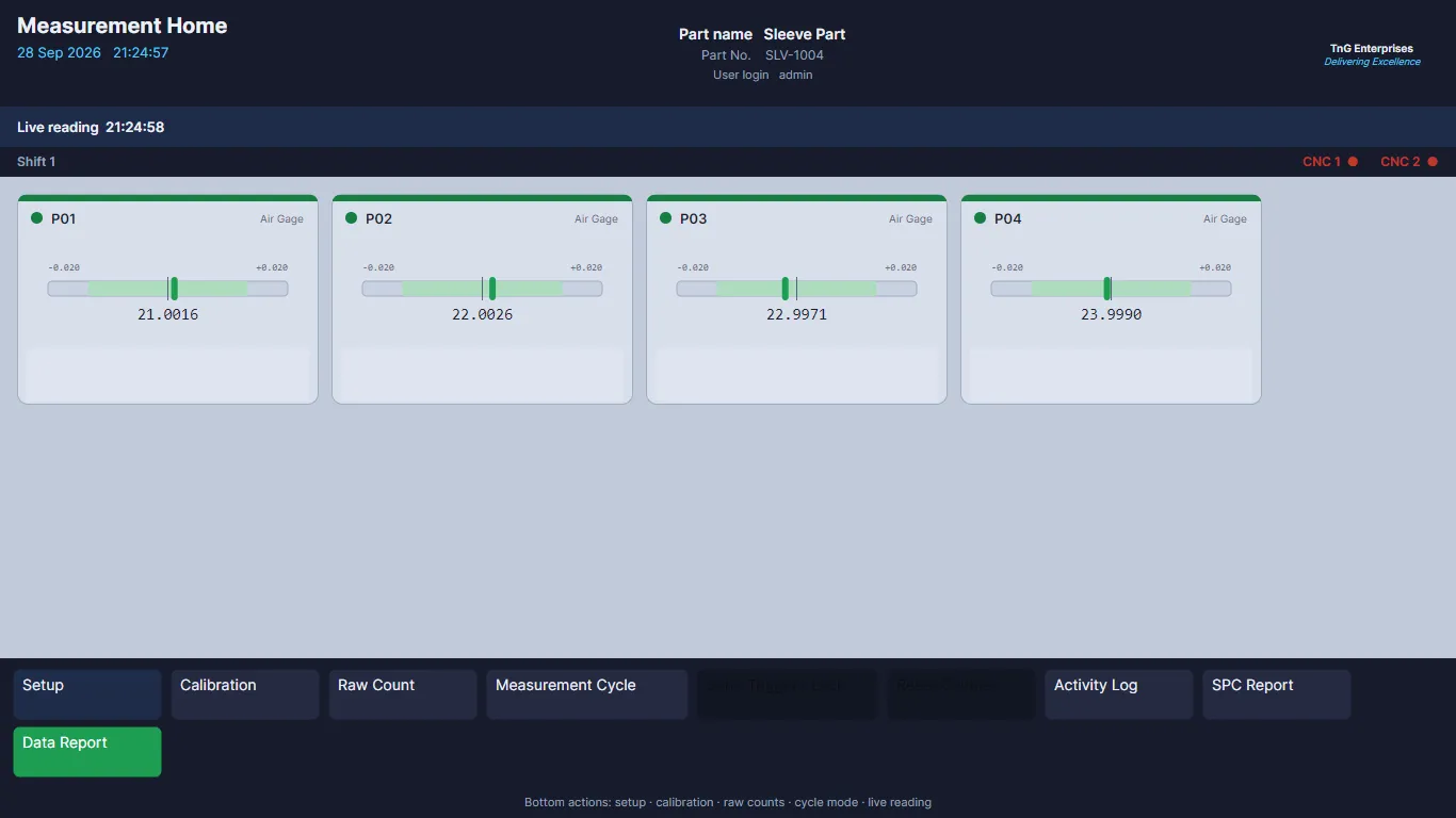
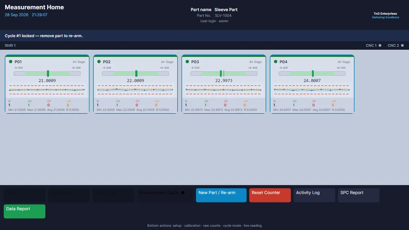
Each part parameter carries its own setup: nominal, upper and lower tolerance, upper and lower control limits, correction direction, offset register, offset frequency and maximum correction clamp. The operator only measures the part. The system does the rest.
Tolerance and control zones
Every measured value falls into one of five zones. The response depends on the zone:
- Green (inside the control limits): a zero correction is written. A stable process is left alone, so normal variation never causes adjustments.
- Yellow (between control limit and tolerance): the part is good, but the process is drifting. A correction is calculated and written before the next part goes out of tolerance.
- Red (outside tolerance): the part is rejected. The correction is written, the rejection is recorded, and alerts and red-bin interlocking can be triggered.
Correction limits and safeguards
Automatic does not mean uncontrolled. Before any write, the system applies:
- Control-limit gate. A non-zero correction only starts after a result leaves the green zone.
- Maximum correction clamp. A large calculated correction is limited to the configured maximum.
- Offset frequency. Correct after every part, or only after a selected number of measured parts.
- Direction per parameter. Positive or negative setup handles different tool and feature behaviour.
- Bad-file protection. Results without a valid part number are ignored.
- Connection test. The CNC connection can be tested before production, and every failed write is logged with its return code.
Traceability for every part
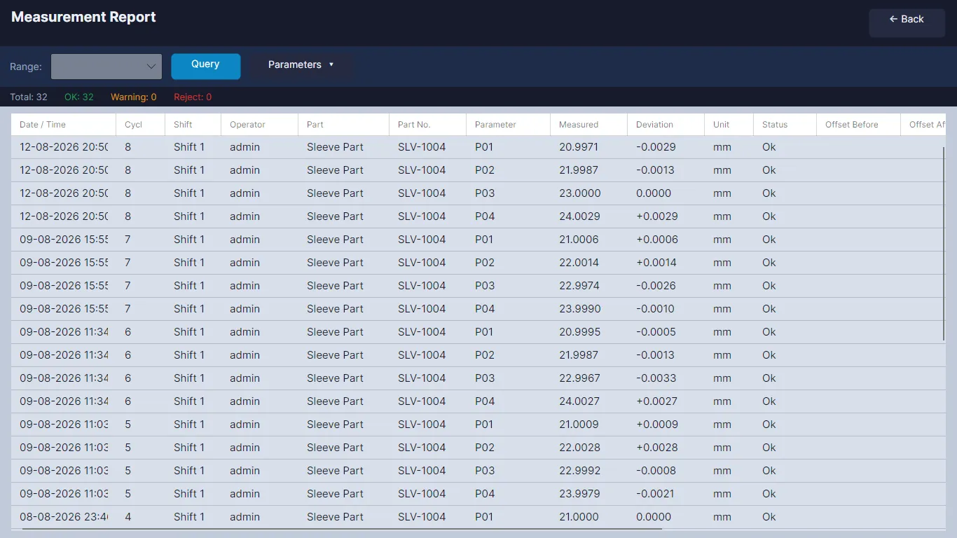
Each measured part leaves a complete record: part number, source and time; nominal, tolerance, control limits and measured value; raw and clamped correction, direction and register; and whether the CNC write succeeded, was skipped or failed. Reports can be filtered by date and exported to CSV for customer audits.
Quality dashboard and alerts
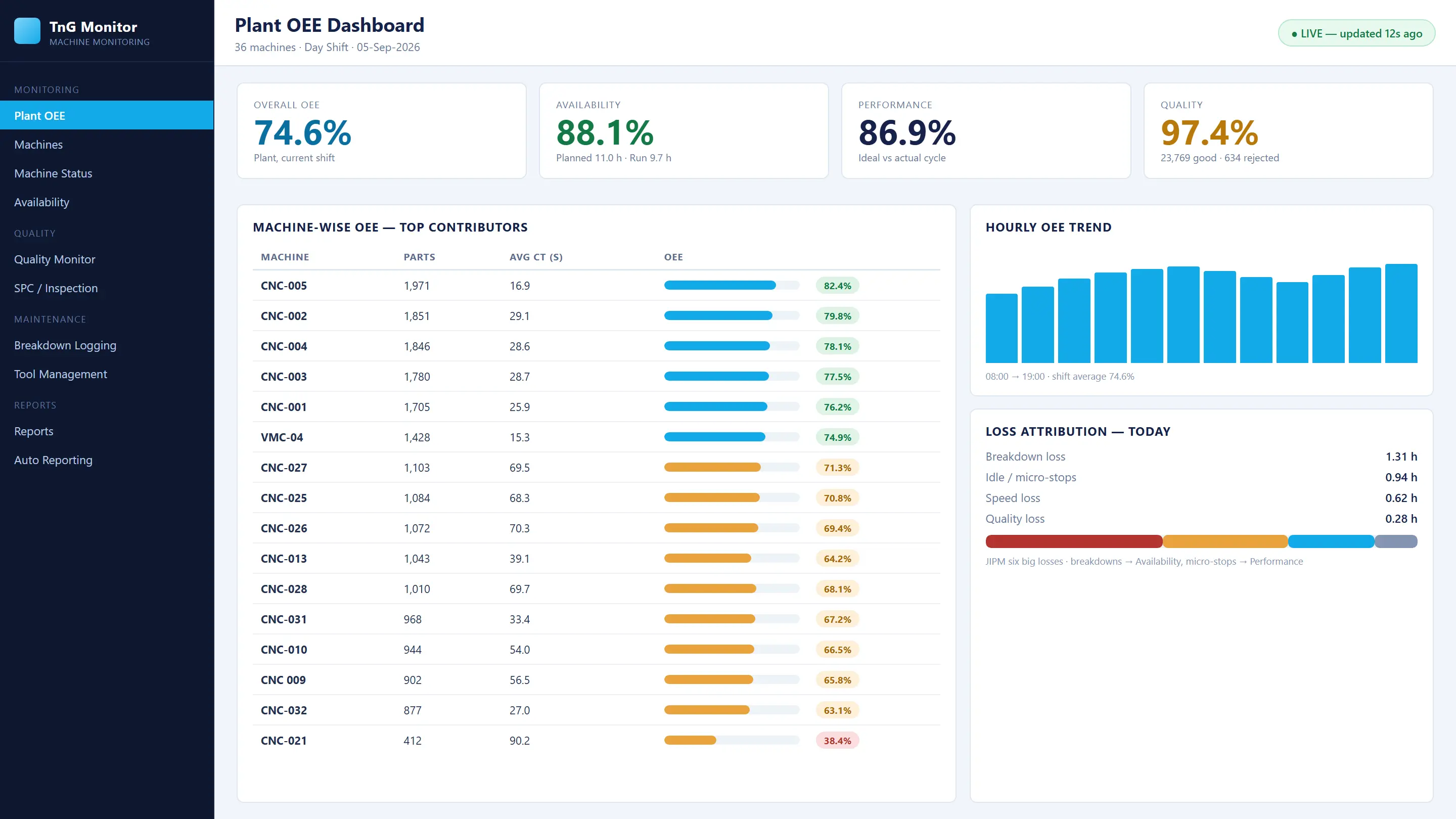
Connected to TnG Machine Monitoring, every reading also feeds the online quality dashboard and SPC, the OEE quality rate and part-wise reports. Optional SMS and WhatsApp alerts cover CNC communication failure, an idle gauge and repeated NG parts.
Compatibility
- CNC controls: FANUC, Siemens, Mazak and other controls, assessed per machine.
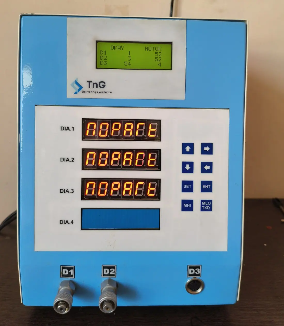
- Gauges: TnG smart digital gauges (piezo, probe, LVDT), and digital gauges of other manufacturers through TnG Offset Master.
- Machines: CNC turning, grinding and other processes where a measured dimension is controlled by a tool wear offset.
Two ways to get it
- New gauging station: a TnG Smart Gauging System with automatic wear compensation built in.
- Existing gauges: TnG Offset Master turns the digital gauges you already own into smart gauges.